1. Overall
| 1 | Cover |
| 2 | Brush strip |
| 3 | Track |
| 4 | Recessed cover clip |
| 5 | Sidelite gasket |
| 6 | Self-close cable unit |
| 7 | Filler panel |
| 8 | View protection profile |
| 9 | End stops |
| 10 | View protection clip |
| 11 | Carriers |
| 12 | Dormotion unit |
| 13 | Sidelite section profile |
| 14 | Floor guide |
| 15 | U-channel |
| 16 | Self-close hold open ball |
| 17 | Self-close cable connector |
| 18 | Self-close cable unit |
| 19 | Start/stop |
2. Installing end stops
| Handing the [opening side] end stop: | |
| 1 | Determine closing edge of door. • SELF-CLOSE END STOP WILL BE USED ON OPENING SIDE OF DOOR. |
| 2 | Hand self-close end stop by inserting bumper on appropriate side of end stop. |
| Install both end stops: | |
| 3 | Slide self-close end stop into opening side of track. |
| 4 | Slide appropriate standard end stop into closing side of track. |
NOTE: Loosen bottom section of end stop for easier install.
NOTE: Be sure set screw is flush with back of bumper.
NOTE: Exact location/adjustments will be determined in Adjustment End Stop location..
3. Securing sidelite adhesive gasket to track
| 1 | Ensure the track is cut to proper length. NOTE: SEE DIMENSION INSTRUCTIONS BELOW |
| 2 | Cut adhesive gasket equal to sidelite glass width. |
| 3 | Adhere gasket along bottom edge of back of track. |
4. Securing sidelite section profile to track
| 1 | Align sidelite profile holes with track profile holes. NOTE: Holes will be predrilled every 7-7/8” [200] |
| 2 | Secure with 9/16” [14] fasteners provided. |
NOTE: Be sure fastener heads are flush with track to avoid rollers catching protruding fasteners.
5. Secure track and sidelite extrusion into ceiling(and drop ceiling extrusion, if supplied)
6. Specifications for securing track to mounting surface
| 1 | Ensure track is properly level and secure it to the header mounting surface per the appropriate measurements on the following page. |
| 2 | Use appropriate fasteners according to the following recommendations. |
NOTE: SEE DIMENSION INSTRUCTIONS ON NEXT PAGE FOR REFERENCE.
NOTE:
OVERHEAD REINFORCEMENT:
The overhead reinforcement must be a minimum of ¼” [6] x 3” [76] steel angle, 16 gauge metal stud with wood blocking, or two pieces of 1 1/2” [38] thick wood blocking (double stacked), secured to studs or joists on a maximum 16” [406] centers for the length of the track. The overhead reinforcement may be flush on the overhead surface or on the interior of this surface.
Track mounting screws must fully penetrate the steel angle, metal stud, or at a minimum of 2” [51] into wood blocking, utilizing the predrilled holes in the MUTO track.
Consult with a structural engineer to determine if reinforcement is adequate for your specific application or to meet specific codes in your location.
7. Door/wall dimensions
8. Installing U-channel for sidelite
| 1 | Install gaskets as shown. Trim to correct length. |
| 2 | Secure u-channel to floor using appropriate fasteners. |
NOTE: Ensure u-channel is plumb and the back of the u-channel profile aligns with back of sidelite profile.
NOTE: Gaskets are pre-installed.
9. Installing roller carriers: on monolithic glass ONLY
NOTE: FULLY CLEAN SURFACE OF GLASS WITH AN ALCOHOL-BASED MILD GLASS AND SURFACE
CLEANER. ENSURE NO DEBRIS IS ON THE GASKET
| 1 | Slide roller carriers onto glass. |
| 2 | Slide glass gasket and metal shim between glass and roller carrier |
| 3 | Secure roller carriers to glass at 10 ft lbs (14 Nm). |
NOTE: Orient gasket with rubber side facing the glass.
10. Installing roller carriers: on tempered laminate glass ONLY
NOTE: THE RECOMMENDED ADHESIVE’S SET-UP TIME IS 20 MINUTES FOR THE DUO-PAK CARTRIDGES.
NOTE: USE 1:1 RATIO PLUNGER WITH THE 3M™ Scotch-Weld™ Urethane Adhesive.
NOTE: FULLY CLEAN SURFACE OF GLASS WITH AN ALCOHOL-BASED MILD GLASS AND SURFACE
CLEANER. ENSURE NO DEBRIS IS ON THE GASKET
| 1 | Slide carriers onto glass. |
| 2 | Replace existing gasket with TLG gasket. |
| 3 | Slide laminated glass gasket and metal shim between glass and roller carrier. NOTE: Orient gasket with rubber side facing the glass. |
| 4 | Replace existing set screws with vented set screws. |
| 5 | Tighten vented set screws at 4 ft lbs (5Nm). NOTE: Onto scrap material, first dispense approximately 12” of 3M™ Scotch-Weld™ Urethane Adhesive prior to application prevent mixing errors and ensure optimal hardening. |
| 6 | Dispense into vented set screws on both sides of carrier. NOTE: Keep glass flat during curing process. |
11. Installing DORMOTION start/stop
| 1 | NOTE: Determine a pin length based upon how square and plumb the opening is. If required, change pin in start/stop assembly. • Remove hex screws. • Remove existing pin and plate. • Swap in appropriate pin and plate. • Replace hex screws. |
| 2 | Slide start/stop onto glass. |
| 3 | Center equally between the carriers. |
| 4 | Slide glass gasket between start/stop and glass. NOTE: Orient with gasket facing glass. |
| 5 | Secure start/stop via set screws |
12. Disengaging the anti-jump
| 1 | Disengage the anti-jump on roller carrier. |
NOTE: Using the appropriate-size hex key, push antijump adjustment screw IN and turn COUNTERCLOCKWISE 90° to disengage anti-jump.
13. Install glass/rollers in track
14. Install floor guide
REMEMBER ANTI-JUMP IS DISENGAGED!
| 1 | Align centerline of glass with centerline of floor guide. |
| 2 | Be sure the glass is plumb. NOTE: Center of floor guide should be 13/16" [20] off the center of the wall. |
| 3 | Mark appropriate floor guide measurements. |
| 4 | TEMPORARILY REMOVE GLASS AND ROLLERS FROM TRACK (TO ALLOW FOR DRILLING SPACE) |
| 5 | Pre-drill into mounting surface using a 5/16" drill bit. |
| 6 | Secure floor guide anchor with included fasteners. |
15. Install floor guide: continued
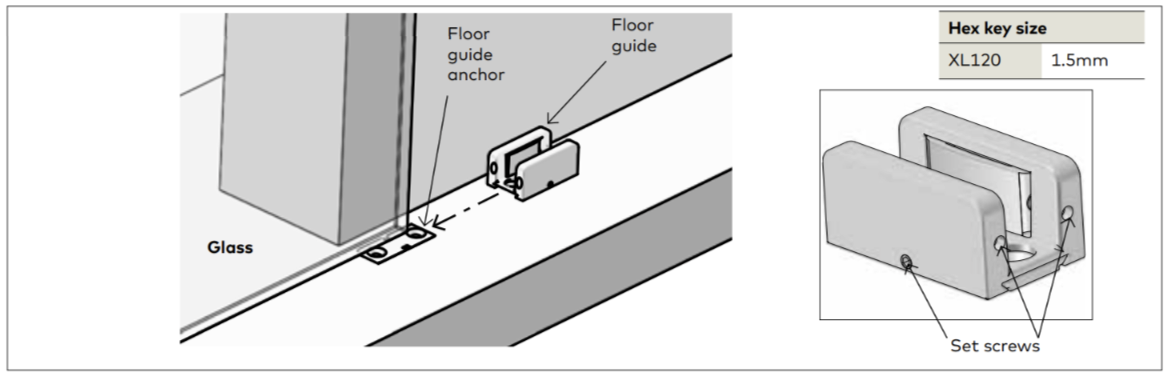
| 1 | Set glass and rollers onto track. |
| 2 | Slide floor guide over floor guide anchor and tighten with set screws. |
| 3 | Remove setting blocks. NOTE: Be sure glass is centered in floor guide. |
16. Engaging anti-jump
| 1 | Engage anti-jump on roller carrier NOTE: Using the optional ratchet and [one of the] provided bits, push anti-jump adjustment screw IN and turn CLOCKWISE 90° to engage anti-jump |
17. Adjustment door height
| 1 | Set height of glass door. |
| 2 | Using the optional ratchet and [one of the] provided bits, loosen height adjustment locking screws of carrier |
| 3 | Using optional ratchet and [one of the] provided bits, turn height adjustment screw CLOCKWISE or COUNTER-CLOCKWISE to raise or lower glass. |
NOTE: Be sure glass is level during this adjustment.
18. Adjustment end stop location: LEADING end stop
Adjustment end stop location: TRAILING end stop
19. Install RH DORMOTION unit - door closed
Fig: 1 RH DM unit
Fig: 2 RH DM unit fastening plates rotated
Fig: 3 RH DM unit inserted in track
Fig: 4 DM unit hook positioned in trigger
Fig: 5 DM unit end stop and hook separation adjustment
Fig: 6 RH DM unit fastening plates secured in track
Fig: 7 RH DM unit aligned in track
Fig: 8 RH DM unit installed in track
| 1 | Rotate RH DM fastening plates. • Using 4 mm hex key, loosen fastening plate hex screws. • Rotate fastening plates until they are parallel to the DM unit (Fig. 2) • Snug hex screws. |
| 2 | Move door to close position. • For installation of RH DM unit, door must be in the closed position against bumper. |
| 3 | Align DM unit in track, engage DM hook in DM trigger. • Align DM unit in track (Fig. 7). • Slide DM unit over the DM trigger block until the DM hook engages the DM trigger (Fig. 4) |
| 4 | Use adjustment tool to set DM unit final position. • Place adjustment tool flat against DM unit with fork between DM hook and DM end stop (Fig. 13.5). • Slide DM unit over until hook and DM end stop are against the fork. This sets 5 mm gap (fork gap). • Trigger height: Adjust so trigger sets on top of adjustment tool. |
| 5 | Secure the DM unit in position. • NOTE: Insure door is fully closed against bumper before performing this step. • Using 4 mm hex key, tighten DM unit fastening plate socket head cap screws. Fastening plates must engage the track (Fig. 6 and 8). Torque Socket head cap screws 3 ft lbs [4 Nm] |
20. Install optional LH DORMOTION unit in opening cycle
Fig: 9 LH DM unit
Fig:10 LH DM unit fastening plates rotated
Fig:11 LH DM unit inserted in track
Fig:12 DM unit hook positioned in trigger
Fig:13 DM unit end stop and hook separation adjustment
Fig:14 LH DM unit fastening plates secured in track
Fig. 15 LH DM unit aligned in track
Fig. 16 LH DM unit installed in track
| 1 | Rotate DM fastening plates. • Using 4 mm hex key, loosen fastening plate hex screws. • Rotate fastening plates until they are parallel to the DM unit (Fig. 2) • Snug hex screws. |
| 2 | Move door to open position. • For installation of LH DM unit, door must be in the open position against bumper. |
| 3 | Align DM unit in track, engage DM hook in DM trigger. • Align DM unit in track (Fig. 7). • Slide DM unit over the DM trigger block until the DM hook engages the DM trigger (Fig. 4) |
| 4 | Set DM unit final position. • Place adjustment tool flat against DM unit with fork between DM hook and DM end stop (Fig. 5). • Slide DM unit over until hook and DM end stop are against the fork. This sets 5 mm gap (fork gap). • Trigger height: Adjust so trigger sets on top of adjustment tool. |
| 5 | Secure the DM unit in position. • NOTE: Insure door is fully open against bumper before performing this step. • Using 4 mm hex key, tighten DM unit fastening plate socket head cap screws . Fastening plates must engage the track (Fig. 8). Torque Socket head cap screws 3 ft lbs [4 Nm] |
21. Adjust start/stop pin height (if necessary)
22. Install self-close hold open clamp
| 1 | Secure self-close hold open clamp to the end stop furthest from latch [closing side]. • Use two screws and tighten to 2.5 ft lbs (3Nm). |
23. Install self-close unit hold open ball
| 1 | Secure self-close hold open ball to carrier furthest from latch [closing side]. • Use two screws and tighten at 2.5 ft lbs [3Nm]. |
24. Install self-close unit cable connector
| 1 | Secure self-close hold open ball to carrier furthest from latch [closing side]. • Use two screws and tighten at 2.5 ft lbs [3Nm]. |
25. Install self-close cable unit
| 1 | Secure self-close cable unit into first groove of MUTO track. |
| 2 | Rotate plates inside track channel to engage. • Use three screws/plates and tighten at 3 ft lbs (4 Nm). |
26. Prepare self-close cable unit
| 1 | Pull "end of cable" over to connect with cable connector. |
| 2 | Continue to pull cable through connector to either increase or decrease self-closing tension. |
27. Adjust tension in self-close cable unit
| 1 | To adjust tension in cable unit cord if necessary, pull 'beginning knot of cable' through cable holder. |
| 2 | Secure another 'knot' and pull cable through holder as show in image above. |
| 3 | Secure beginning 'knot' in holder clamp. NOTE: Be sure there is a 7-7/8" [200] gap between each new 'knot' in the cord. |
28. Secure drop ceiling extrusion to cover
| 1 | Pre-drill holes through cover groove into drop ceiling extrusion. • End holes: approximately 2” [51] from end of cover • All other holes: approximately 12” [305] apart |
29. Install recessed mount cover clips
| 1 | Slide cover clips on from end of cover. |
| 2 | Tighten with screw. Be sure not to damage cover. NOTE: 1 clip per 2 feet of cover extrusion. |
30. Install brush profile
| 1 | Measure and cut brush to appropriate length. |
| 2 | Slide brush into cover. |
31. Install view protection clips
TO BE USED WITH ONE OR MULTIPLE SIDELITE APPLICATIONS.
| 1 | Slide door open until it meets the end stop. |
| 2 | Measure and cut view protection profile to fit into empty sliding portion of track - 3/16" [5]. |
| 3 | Snap view protection clips onto inside of cover as shown. |
| 4 | Use minimum 1 clip per foot of profile. Exception: If profile is minimum of 1 foot in length, use 2 clips. |
32. Cover spacers
| 1 | Tip cover spacers into outer most edge of track. |
| 2 | Place one at each end of track as shown. |
| 3 | Tighten at at 1 ft lbs [1Nm] or hand tighten. |
33. Install cover and view protection profile
| 1 | Install cover: • Insert back prong lip of recessed cover clip into groove first. • Rotate cover assembly up and then snap front prong lip of clip into track groove. |
| 2 | Once cover is in place, tip view protection profile up in between track and cover. |
| 3 | Snap down into cover and onto track as shown. |
34. Install end caps
| 1 | Snap end caps into cover. |
| 2 | Snap end caps into ends of sidelite profile. |
| 3 | Snap end caps into ends of u-channel. |
35. Installing sidelite glass
| 1 | Place setting blocks into u-channel. |
| 2 | Spray inside of u-channel with glass cleaner. |
| 3 | Lift glass up and into sidelite profile. |
| 4 | Lower glass into u-channel. |
| 5 | Ensure there is 1/8" [3] gap between wall and edge of sidelite glass. |
| 6 | If using tempered laminated glass, gently press glass against u-channel gasket, and dispense silicone along full length of non-gasket side of u-channel. |
36. Installing sidelite glass gasket
| 1 | Cut gasket to length. |
| 2 | Press gasket in between sidelite glass and sidelite profile. |
37. Installing sidelite glass filler panel
| 1 | Fit filler panel between empty section of track and sidelite profile, on door side. |