Mounting
Mortise Installation (Solid Wood)
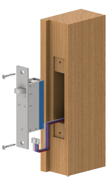
- Cutting the mortise
Referring to the product dimension drawings, a mortise is cut into the door frame to fit the lock and a mortise is cut into the door leaf to fit the strike. Wooden doors and frames require full mortises with space made behind the lock body to accommodate the wire connections.
It is crucial to ensure that the mortises in the door leaf and frame are aligned vertically and horizontally when the door is closed as this aligns the bolt pin to the strike opening and also the strike magnet to the locks internal door position sensor.
Ensure that the final gap between the lock face plate and strike plate once it is installed will be no more than 6mm (1/4 inch). - Wiring the lock
A hole needs to be drilled in the back of the mortise to bring the wires out and a connection can be made to the supplied wire loom which in turn plugs into the lock.
Refer to the Wiring section of this document for detailed instructions on wiring. - Setting the operating mode
Ensure the operating mode switch is positioned to the required state, Fail Safe or Fail Secure.
Refer to the Operating Mode section of this document for detailed instructions on wiring. - Fitting the lock and strike plate
The lock can be slid back into the door frame mortise, ensuring that the wiring integrity is maintained, and then secured in place with the supplied 10G self-tapping screws. Please ensure the lock is the correct orientation as to pull the door into the door jamb.
The strike is then placed into the door leaf mortise and the remaining 10G self-tapping screws are used to secure it in place. Ensure the strike is oriented so that the bolt hole aligns with the lock bolt.
Mortise Installation (Metal Extrusion)
- Cutting the mortise
Referring to the product dimension drawings, a mortise is cut into the door frame to fit the lock and a mortise is cut into the door leaf to fit the strike. Metal doors and frames, being hollow, often only require a single rectangle cut-out to accommodate the lock face plate or strike plate. For these installations lock and strike can be installed flush using fitting tabs (available separately).
It is crucial to ensure that the mortises in the door leaf and frame are aligned vertically and horizontally when the door is closed as this aligns the bolt pin to the strike opening and also the strike magnet to the locks internal door position sensor.
Ensure that the final gap between the lock face plate and strike plate once it is installed will be no more than 6mm (1/4 inch). - Wiring the lock
Feed the wires out of the hollow chamber of the frame and a connection can be made to the supplied wire loom which in turn plugs into the lock.
Refer to the Wiring section of this document for detailed instructions on wiring. - Setting the operating mode
Ensure the operating mode switch is positioned to the required state, Fail Safe or Fail Secure.
Refer to the Operating Mode section of this document for detailed instructions on wiring.
- Fitting the lock and strike plate
The lock can be placed into the door frame cutout, ensuring that the wiring integrity is maintained, and then secured in place with M5 machine screws (included with fitting tabs). Please ensure the lock is the correct orientation as to pull the door into the door jamb.
The strike is then placed into the door leaf cutout and then M5 machine screws (included with fitting tabs) are used to secure it in place. Ensure the strike is oriented so that the bolt hole aligns with the lock bolt.
Surface Mounting Installation (Solid Wood)
- Preparing the mounting surface
Install two 10Gx1” self-tapping screws (included with housing) in the mounting surface, as per the product dimension drawings they should be 125mm apart, 20mm from the surface edge. - Preparing the housing
An 8mm hole should be drilled through the housing wall at the position chosen by the installer for the wiring to enter. The wiring can be guided to the housing through surface mount conduit, or through a hole in the mounting surface material. Push a rubber grommet (included with housing) over the drilled hole to protect the wires from any sharp edges. - Fitting the housing
Position the keyhole cutouts of the housing over the screw heads and slide into position flush with the surface edge, and then tighten screws in place to secure the housing. - Wiring the lock
Feed the wires through the 8mm hole in the housing and a connection can be made to the supplied wire loom which in turn plugs into the lock.
Refer to the Wiring section of this document for detailed instructions on wiring. - Setting the operating mode
Ensure the operating mode switch is positioned to the required state, Fail Safe or Fail Secure.
Refer to the Operating Mode section of this document for detailed instructions on wiring. - Fitting the lock
The lock is then placed into the housing, ensuring that the wiring integrity is maintained, and then secured in place with M5 machine screws (included with housing). Please ensure the lock is the correct orientation as to pull the door into the door jamb.
Surface Mounting Installation (Glass)
- Fitting the housing
Clean the glass surface with isopropyl alcohol and peel the protective layer from the double sided tape of the housing. Position the housing flush with the edge of the glass, and press down to adhere tape to surface. - Fitting the dress plate
Clean the glass surface with isopropyl alcohol and peel the protective layer from the double sided tape of the dress plate. Position the dress plate flush with the edge of the glass and centered on the housing location, and press down to adhere tape to surface. - Fitting the strike plate
The strike is then placed into the housing and then secured in place with M5 machine screws (included with housing). Ensure the strike is oriented so that the bolt hole aligns with the lock bolt.