1. Installation instructions
| 1 | Cover |
| 2 | Brush strip |
| 3 | Track |
| 4 | End cap |
| 5 | End stop |
| 6 | Cover clips |
| 7 | Start/stop guides |
| 8 | Roller carrier |
| 9 | Wood door adaptor |
| 10 | Wood door anti-jump |
2. Securing wood door adaptor
NOTE: Top of door must be reinforced to secure wood door adaptor.
NOTE: Seal top and bottom of door to minimize warping. (Use wood door manufacturer’s recommendations.)
| 1 | Prepare door properly for wood door adaptor. |
| 2 | Cut wood door adaptor to be equal width of door. |
| 3 | M50: • Secure wood door adaptor to top of wood door with #10 x 3” wood screws. NOTE: Be sure screws are always secured in the first four and last four holes of the adaptor, along with every fourth hole in between. |
3. Securing track to mounting surface
| 1 | Ensure the track is properly level and secure it to the ceiling per the appropriate measurements on the following page. |
| 2 | Use appropriate fasteners according to the following recommendations. |
NOTE: SEE DIMENSION INSTRUCTIONS ON NEXT PAGE FOR REFERENCE.
NOTE:
WALL REINFORCEMENT:
The wall reinforcement must be a minimum of ¼” [6] x 3” [76] steel angle, 16 gauge metal stud, or 1-1/2” [38] thick wood blocking secured to the wall studs on a maximum 16” [406] centers for the length of the track. The wall reinforcement may be flush on the wall surface or on the interior of the wall. For masonry walls the track may be secured directly to the wall with lead anchors.Track mounting screws must fully penetrate the steel angle, metal stud, or wood blocking, utilizing the predrilled holes in the MUTO track.
Consult with a structural engineer to determine if reinforcement is adequate for your specific application
or to meet specific codes in your location.
4. Door/wall dimensions
5. Specifications - technical data
6. Installing roller carriers: on monolithic glass ONLY
NOTE: FULLY CLEAN SURFACE OF GLASS WITH AN ALCOHOL-BASED MILD GLASS AND SURFACE
CLEANER. ENSURE GASKET IS FREE OF DEBRIS.
ENSURE ROLLER CARRIER WHEELS ARE FREE OF DEBRIS.
| 1 | Slide roller carriers onto adaptor. |
| 2 | Slide glass gasket and metal shim between adaptor and roller carrier. NOTE: Orient gasket with rubber side facing the adaptor. |
| 3 | Secure roller carriers to glass using appropriatesize hex key at 10 ft lbs [14 Nm]. |
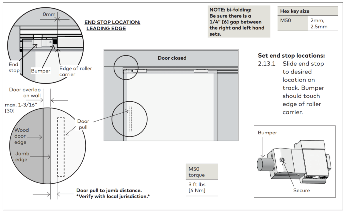
7. Installing end stops
| 1 | Slide end stops into each end of the track. NOTE: DO NOT FULLY TIGHTEN. NOTE: Exact location/adjustments will be determined in “Adjustment End Stop Location” step |
8. Install glass/rollers in track
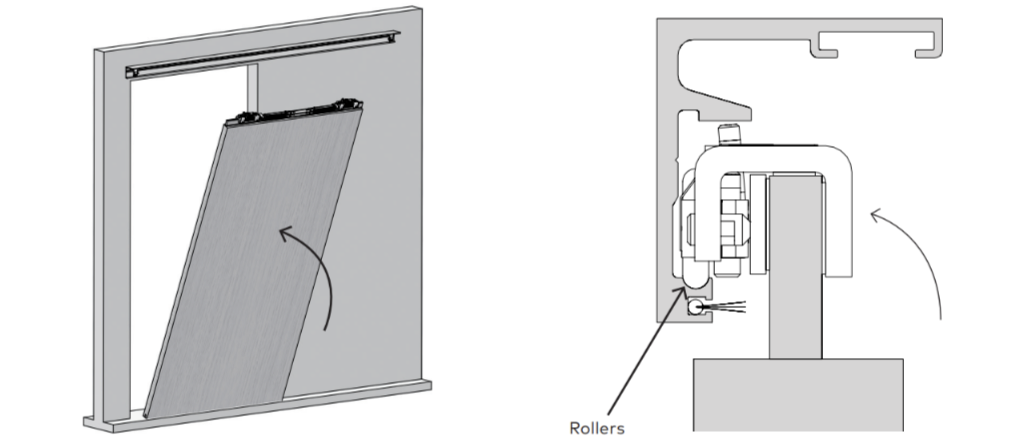
| 1 | Tip door and rollers upward and rest rollers on track. |
ENSURE ROLLERS AND TRACK ARE FREE OF DEBRIS.
9. Engaging anti-jump
| 1 | Temporarily engage anti-jump on roller carrier. |
| 2 | Using appropriate-size ball-end hex key, turn adjustment screw CLOCKWISE to engage anti-jump |
10. Install floor guide
| 1 | Temporarily slide floor guide into bottom groove of wood door. |
| 2 | Be sure the door is plumb. |
| 3 | Mark appropriate floor guide measurements. |
| 4 | DISENGAGE ANTI-JUMP. |
| 5 | TEMPORARILY REMOVE WOOD DOOR AND ROLLERS FROM TRACK |
| 6 | Pre-drill into mounting surface using a 5/16" drill bit. |
| 7 | Secure floor guide anchor with included fasteners. |
11. Secure wood door anti-jump
ENSURE ROLLERS AND TRACK ARE FREE OF DEBRIS.
| 1 | Align wood anti-jump flush with each end of wood adaptor. |
| 2 | Mark and drill holes for anti-jump. • Use a 1/8” drill bit and tap. |
| 3 | Temporarily secure anti-jump to end of wood adaptor via outter most hole. |
| 4 | SET WOOD DOOR BACK ONTO TRACK. |
| 5 | ENGAGE WOOD ANTI-JUMP by turning anti-jump screw CLOCKWISE. Track clearance to be max. 1/32” [0.5]. |
| 6 | Move anti-jump to be flush with end of wood adaptor. |
12. Adjustment door height
| 1 | RE-ENGAGE ROLLER ANTI-JUMP by turning anti-jump adjustment screw CLOCKWISE. NOTE: Anti-jump should NOT touch track. |
| 2 | Set height of door. |
| 3 | Using appropriate-size hex key, turn height adjustment screw CLOCKWISE or COUNTERCLOCKWISE to raise or lower door. NOTE: Be sure wood door is level during this adjustment |
13. Adjustment end stop location: LEADING end stop
Adjustment end stop location: TRAILING end stop
| 1 | Temporarily slide floor guide into bottom groove of wood door. |
| 2 | Be sure the glass is plumb. |
| 3 | Mark appropriate floor guide measurements. |
| 4 | DISENGAGE ANTI-JUMP. |
| 5 | TEMPORARILY REMOVE GLASS AND ROLLERS FROM TRACK. |
| 6 | Pre-drill into mounting surface using a 5/16" drill bit. |
| 7 | Secure floor guide anchor with included fasteners. |
14. Cover clips
| 1 | Insert cover clips into track. (One clip per foot) |
| 2 | Insert perpendicular to track, and turn CLOCKWISE to snap into place. |
15. Install brush profile
| 1 | Measure and cut brush to appropriate length. |
| 2 | Slide brush into track. |
16. Install cover
| 1 | Secure cover to clips and snap into place. NOTE: Roll cover from the bottom upwards. Ensure the bottom of the cover is supported by the groove in the cover clip. |
17. Install end caps
| 1 | Snap end caps onto track. |