991/991N Installation Instructions
Switch Information
Time Adjustment Procedure: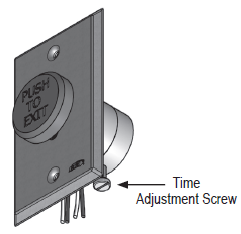
- Use fingers to turn the brass adjustment screw.
- Turn clockwise to increase the delay.
- Tun counterclockwise to decrease delay.
- Like all pneumatic switches, time delays are approximate and can be affected by environmental variables. If in doubt, leave a longer delay to allow sufficient egress time.
Note: The adjustment screw may be facing up or down.
Specifications:
| Time Range | Standard and Narrow 1 sec to 45 sec +/- 15% |
| Repeated Accuracy | +/- % @ 72°F (22° C) |
| Switch Rating | 5 Amp @ 125 VAC |
| Temperature Range | -17°F to +120°F (-27°C to +49°C) |
| Timer Life | 1 million operations |
Hardware Installation
The 991 mounts in a single-gang electrical box with 2 screws. Slotted screws require a standard screw driver. Carefully line up these screws with tans in the electrical box and tighten.
The 991 narrow pushbutton includes a 1/4" filler plate for use in installations as required.
Typical System Control Wiring Diagrams
Electromagnetic Lock, Normally Closed Circuit
Electronic Strike, Normally Open Circuit